Haug530D
-
Innholdsteller
6742 -
Ble med
-
Besøkte siden sist
-
Dager vunnet
3
Innholdstype
Profiler
Artikler
Forum
Galleri
Blogger
Kalender
Alt skrevet av Haug530D
-
Skjønner meg ikke på mennesker som hiver dekka baki setet og tror det blir ett bra resultat likksom
-
Støy over tid kan føre til dødsfall grunnet stress osv.... https://www.adressa.no/nyheter/i/4zkvX9/trafikkstoey-er-livsfarlig Selv lider jeg av en form for Misofoni og støy som andre lager takler jeg egentlig dårlig, så kommer vel til å daue før jeg er 60
-
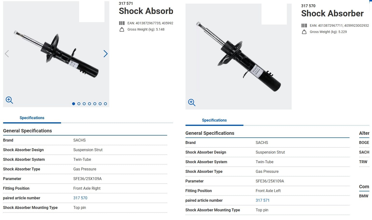
 Om du ser min post ovenfor så er det ikke M-Sport vs Standard, det er høyre/venstre side, forøvrig så har M-Sport og Non Msport samme demper fra Sachs. Se forøvrig sammenligning under
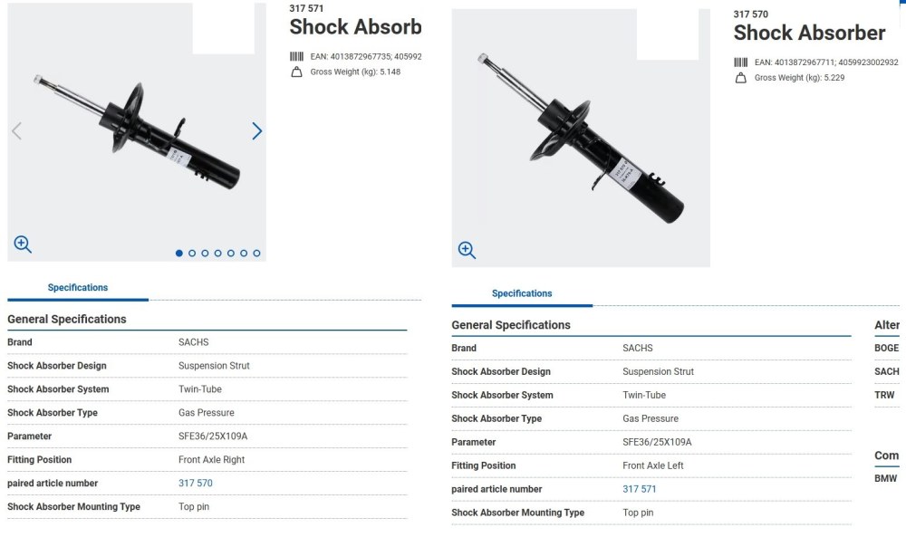
- 29 svar
-
- 1
-

-
Jeg styrer stort sett unna utenlandske selgere jeg også, har ikke noe imot utlendinger men føler de på en måte høyner statistikken for svindel, når det er sagt så var vi hos noen Ukrainere og kjøpte første bilen til jentungen og det var en veldig bra handel , bilen ble til og med overlevert på mitt navn før jeg sendte penger til de, noe jeg selv aldri hadde gjort, nå var det ikke så høy sum (ca 40k for en veldig lite kjørt Peugeot 307) men likevel så hadde nok ikke jeg gjort det ved salg selv, da hadde det vært penger først på konto.
-
Sachs 317571 = 31303451394 Høyre side Sachs 317570 = 31303451393 Venstre side Og jeg vil tippe det skulle stå "Suspension: for vehicles with sports suspension Check OE number"
-
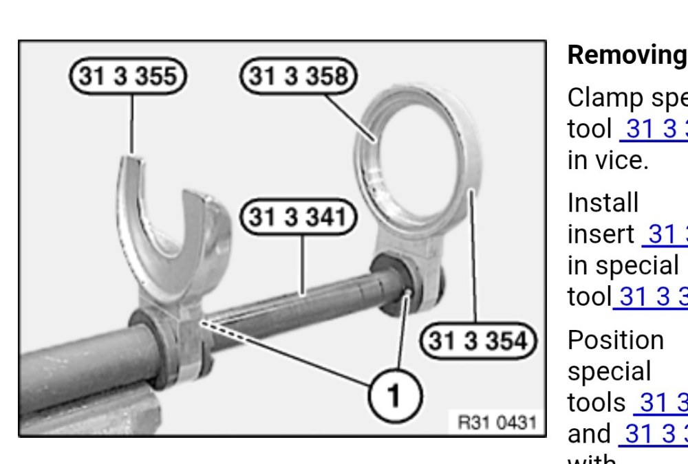
Jeg vet iallefall at det er spesial fjær spenner til E8x har lurt litt på og lage meg skåler som passer bedre til dette settet oppimot E8x, er nok til andre BMW også men jeg føler disse er litt verre enn de andre jeg har byttet på.
-
Blir nok ikke så omfattende bildetråd som din, er som regel mer opphengt i og skru enn og ta bilder jeg Ikke negativt ment altså
- 173 svar
-
- 1
-

-
Ble ikke så fet når den ble kortere og kortere iallefall
- 28207 svar
-
- 11
-

-
Det er da ikke noe heft og bytte fjærer, hadde en Yaris der byttet jeg begge fjærene foran innenfor en time, er litt mer klur og bytte på E87 med det settet som er linket til hos Biltema (Jeg kjøpte forøvrig samme sett hos Aliexpress for over 10 år siden) Ellers så har jeg brukt det på E60 + noen andre biler. Den gangen jeg byttet på E39 som jeg hadde tidligere bestilte jeg både dempere og fjærer, samt tårnlager, dempergummier osv.. og satte alt sammen før jeg skiftet på bil, Det var da Bilstein dempere med Eibach fjærer.
-
Det kan nok være flere forskjeller på N vs mot N, men du har N motor i bilen din, i september 2009 så kom det N motor til E90, så om du velger vrakbil motor fra 2010 E90 og opp så bør du være rimelig sikker, men som sagt så kan det være ting som må byttes over, bunnpanne er iallefall forskjellig på motor E90/E91 Vs F10/F11 Delenummer på motor E90 VS F10 er derfor forskjellig pga disse forskjellene, men i bunn så er det like motorer.
-
E32 750 en sjeldenhet https://bilwebauctions.se/en/novemberauktion-3-2025/bmw-750ia-v12-e32-54558
-
Ladetrykksregulator er no 4 på bildet her, altså den sitter på innsuget. https://www.realoem.com/bmw/enUS/showparts?id=2D71-EUR-03-2015-F46-BMW-220dX&diagId=11_6458
-
Motorene vil jeg tro er like, men om det er som med tidligere 3 og 5 serie motorer så har jo blant annet bunnpanne vært annerledes for eksempel, så det er nok mulig og putte en E9X LCI motor i en F10/F11 ja om man flytter over diverse deler. At du får opp annet svar på 2009 modell skyldes at det er ett skille på N47 vs N47N 09/2009, Innsug er forskjellig mellom N og ikke N motor, F10/F11 er kun levert med N47N motor.
-
Hehe, nei, han har vel holdt det gående i noen år nå, så mest sanylig ett troll ja
-
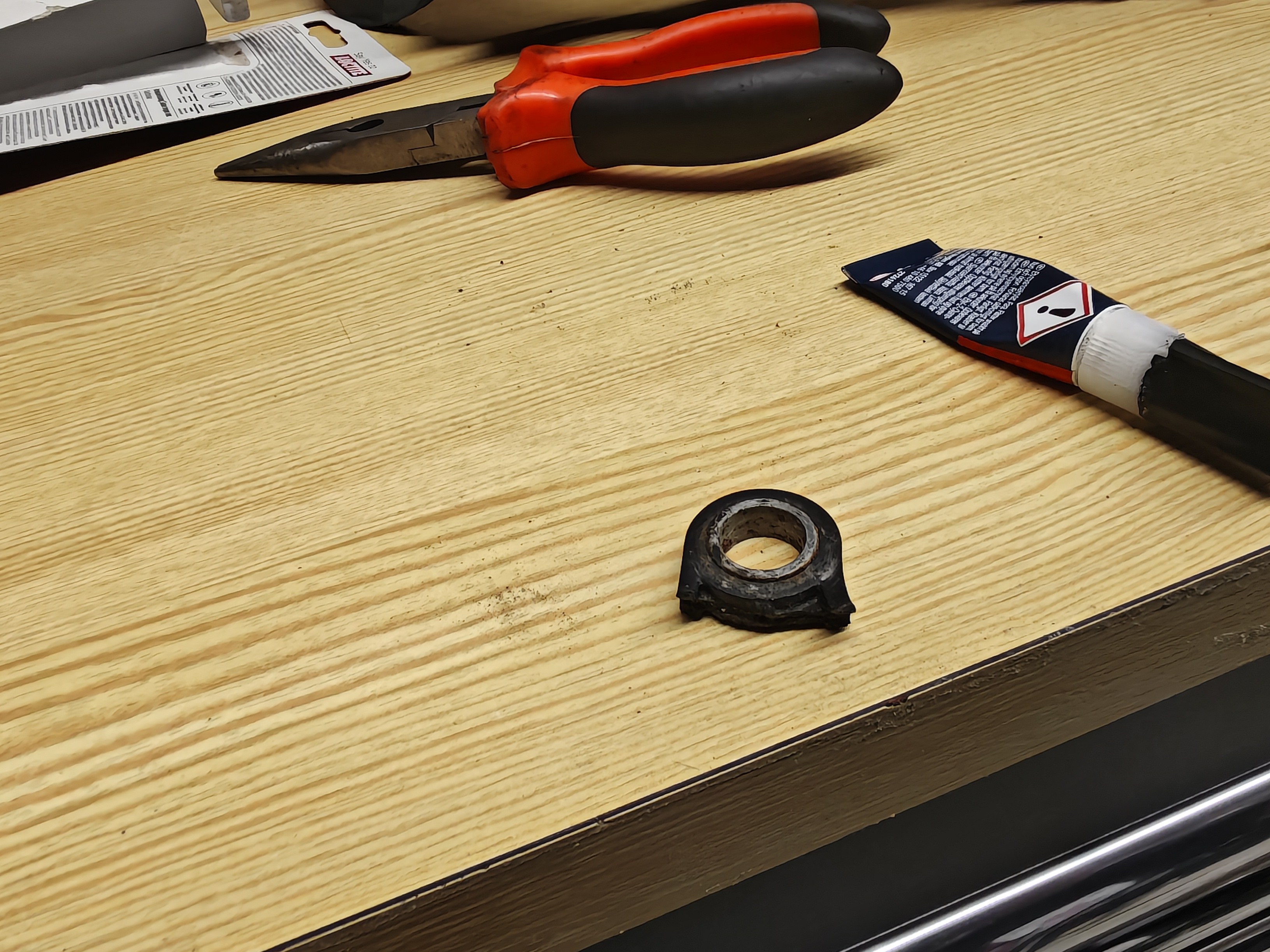
Næh, ble ikke bra, hverken det der eller Den som holder pedalen på E39, den er iallefall laget i POM så vanskleig og lime, så bestilte likesågodt ny pedal holder hos Koed til E39 samt ett brukt motordeksel til E60
-
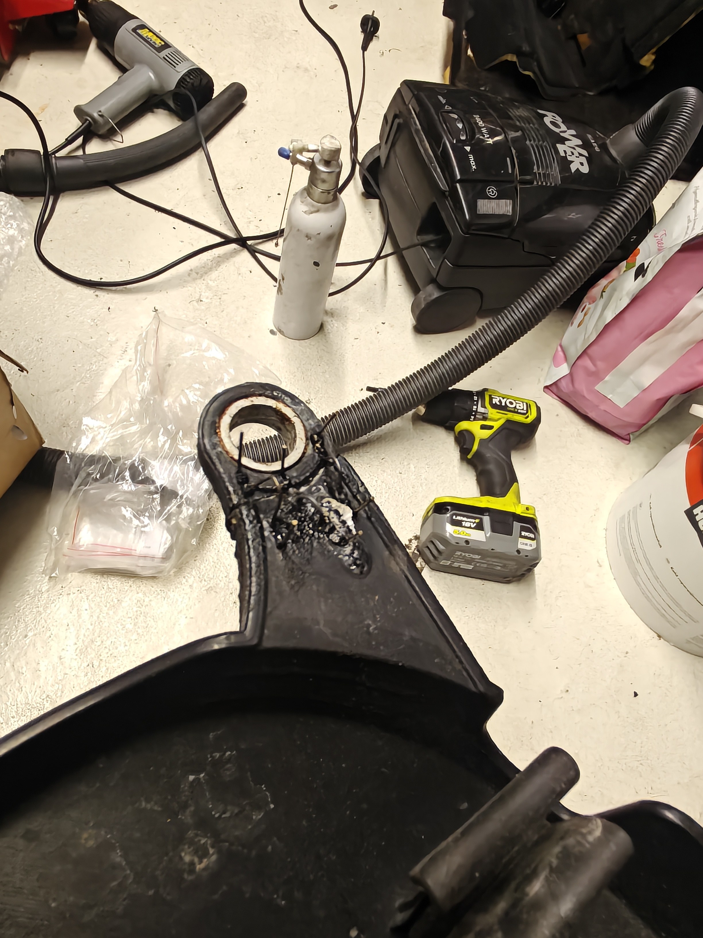
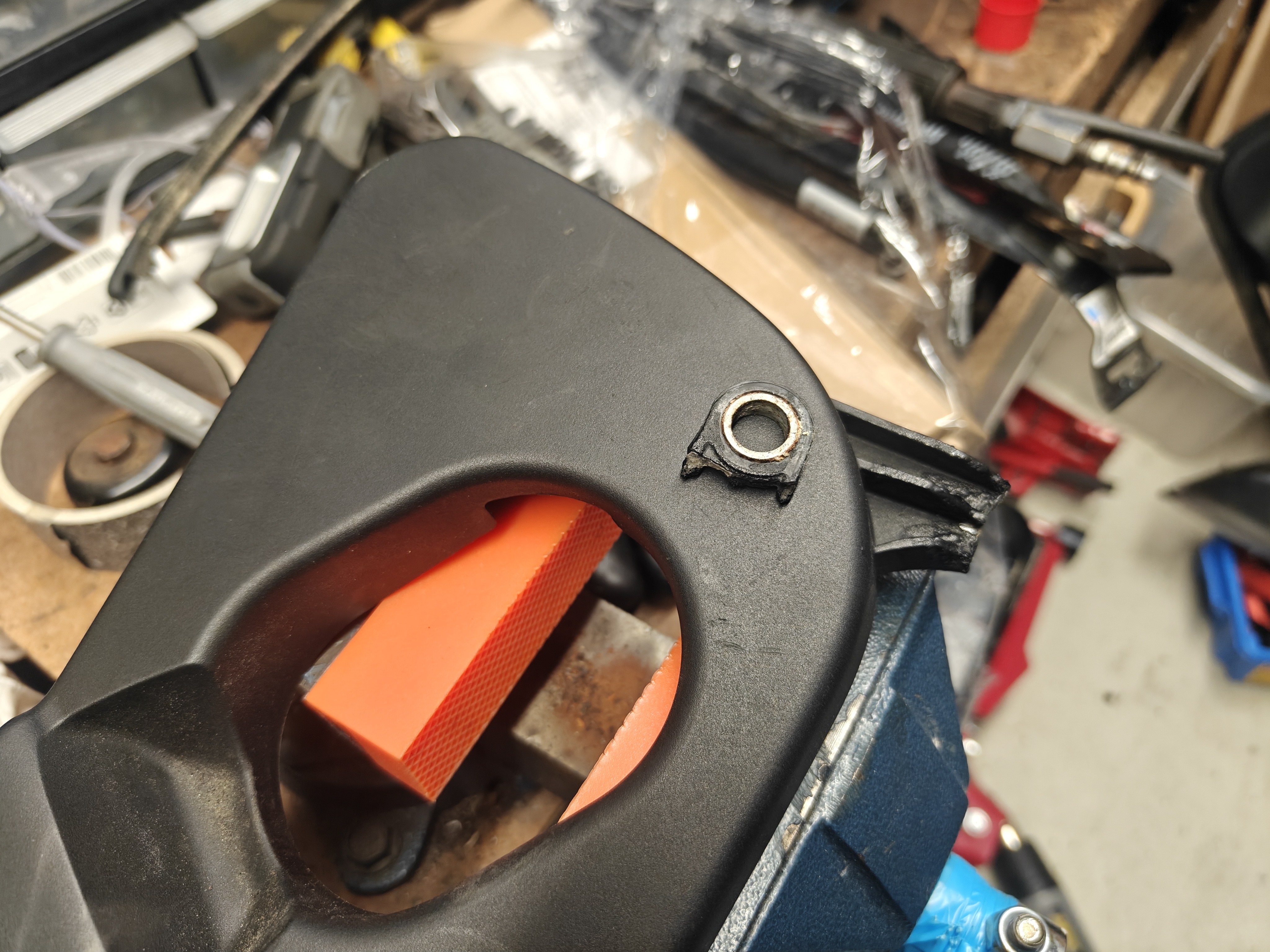
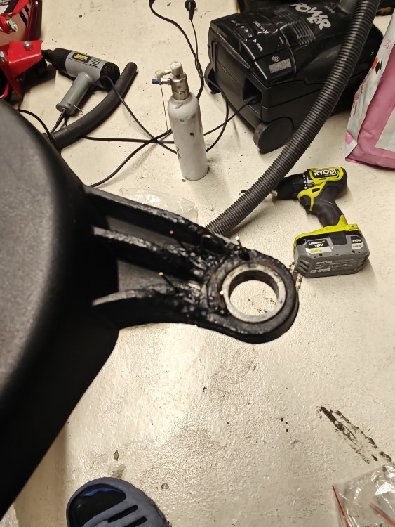
Litt sånn midlertidig fix, limt og plastsveiset, så bøyer jeg bare de stål strengene ned og har ett eller annet over og pusser litt, så blir det sånn tålig ok 😂

-
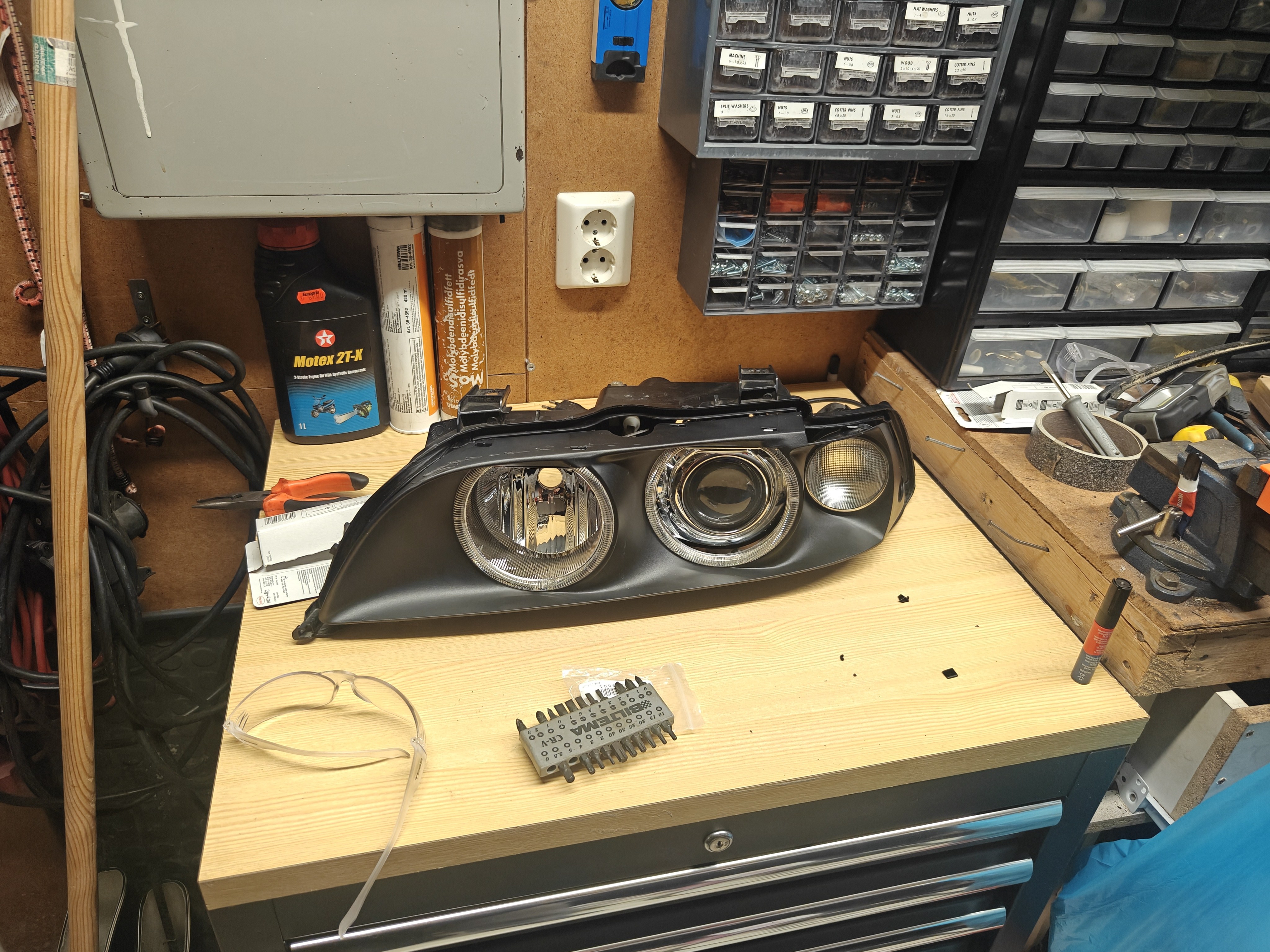
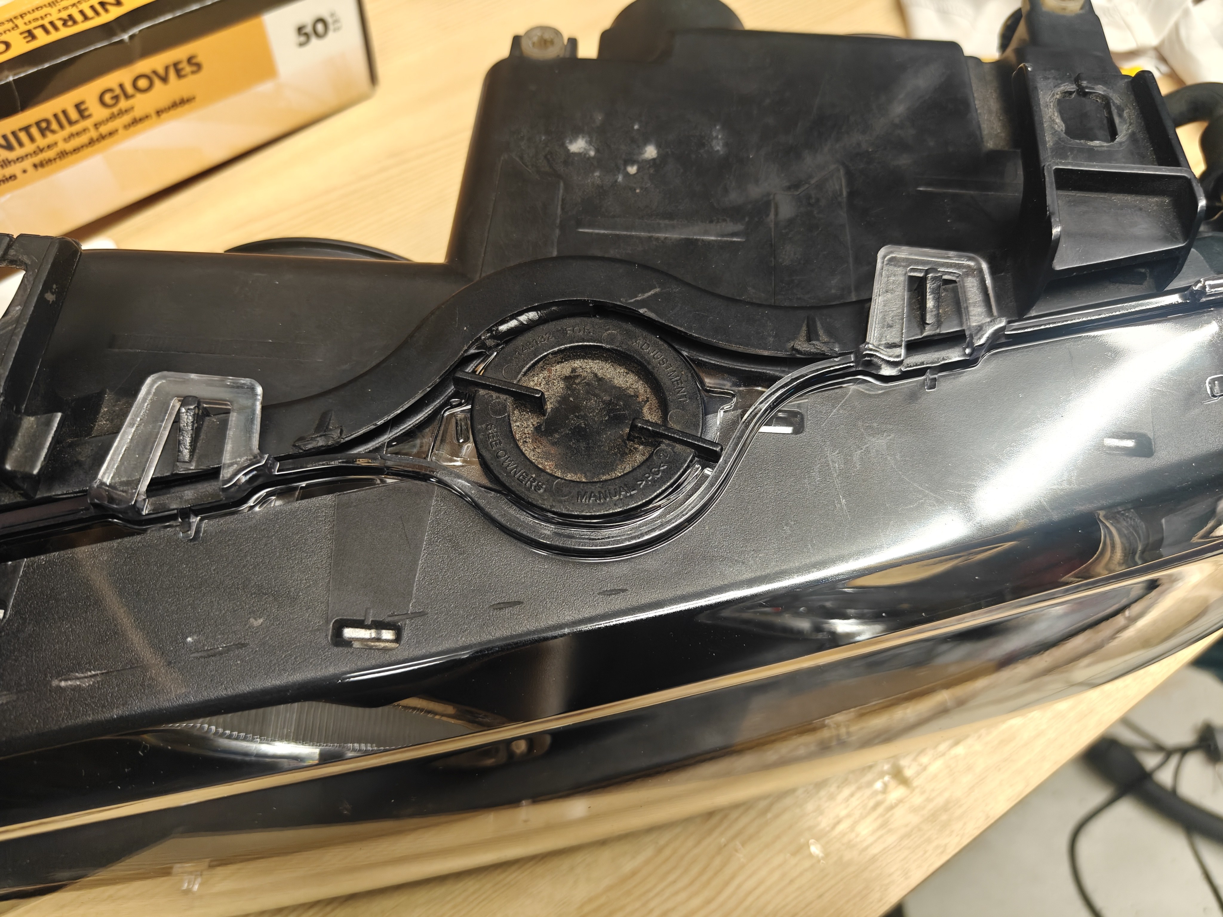
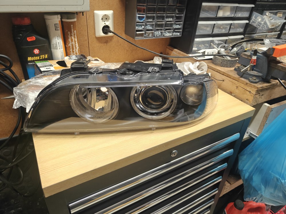
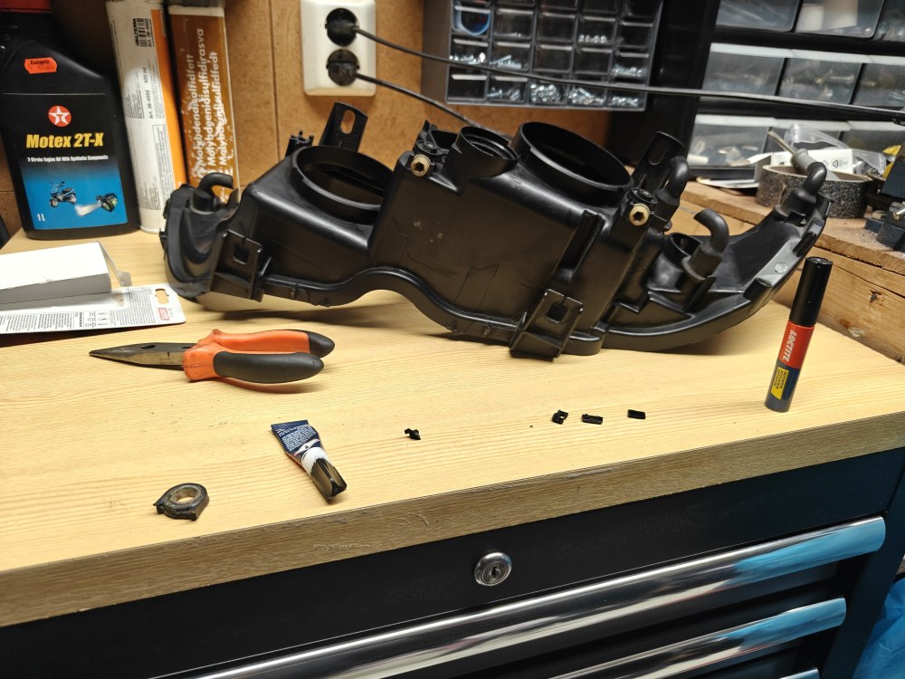
Rimelig fornøyd nå 😃 lykta er nå ferdig "Bitumert" med nytt glass som forøvrig passet meget bra. Før montering av glass Etter Til og med dekslet på toppen passer 100% så i en annen YouTube video en som også brukte bitumen her for og montere, mens her passet lokk og o-ring som hånd i hanske Det knekte festet på ene motor deksel til E60 likte ikke Loctite All plastics så veldig bra, jeg prøvde dog å fremprovosere litt krefter her, mulig det ikke var rent nok, da jeg bare limte uten og gjøre rent, menmen får vel tak i ett nytt brukt så ikke så voldsomt krise.


- 173 svar
-
- 2
-
-
Litt grell farge på stoler og litt undermotorisert for min del, synes 7 serien minimum bør ha V8'er jeg da, men prisen er det nok ikke noe og si på nei.
-
Vil tro at hennes nøkkel da er kortsluttet.
-
Ble litt liming av knekt plast og diverse på lykt til E39, så neste nå blir å sette sammen lykt igjen 🙂 Litt liming deksel til E60 også

-
Eventuelt så kunne man jo alltids laget noe mellomstykke og hatt mellom.
-
Egils BMW tråd - Nylakkede deler ankommet...
emne svarte i Haug530D sin Kolstad Jr. i Bilder og filmer / Show-off
Grattis med ny bil, veldig riktig motor iallefall- 339 svar
-
- 1
-
-
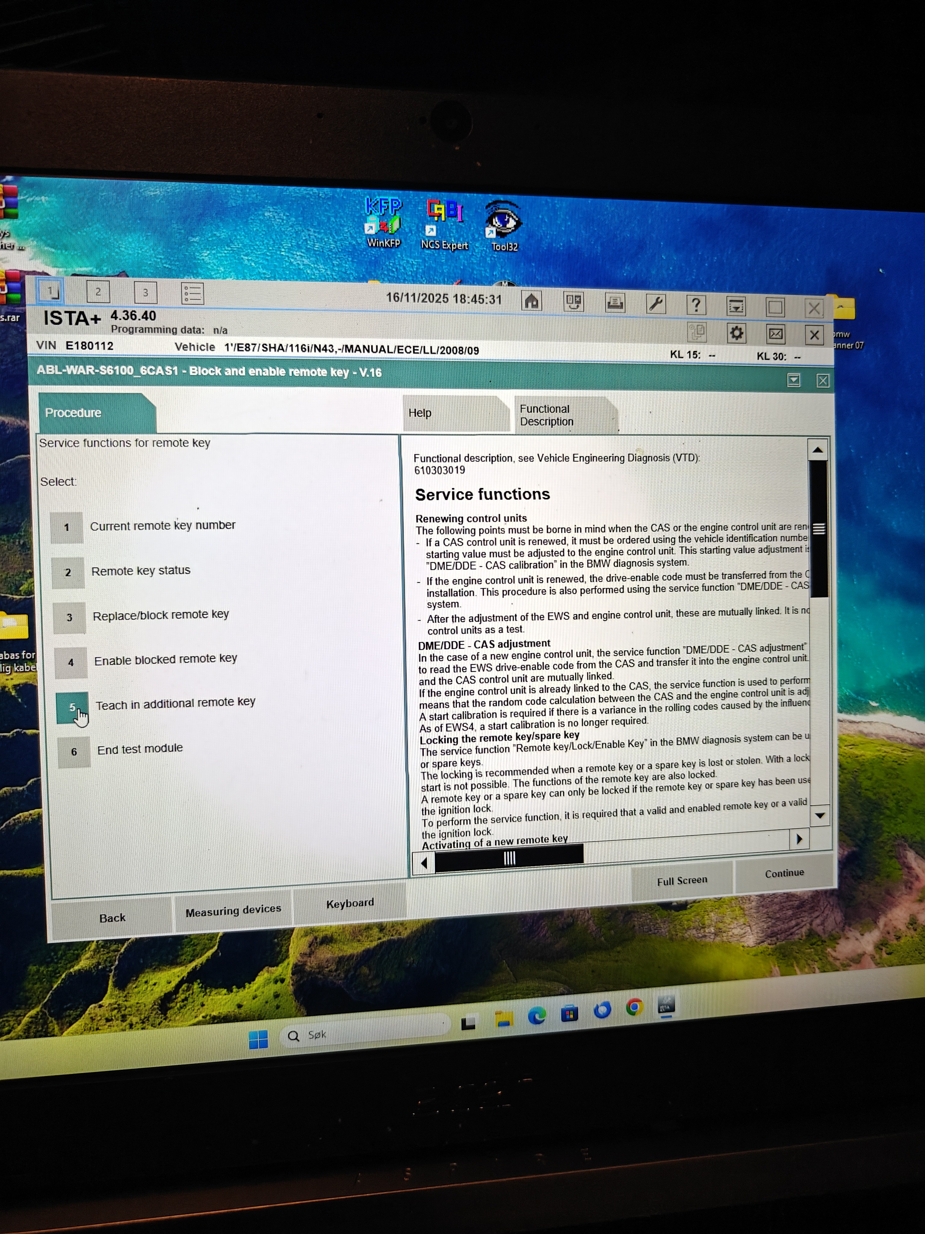
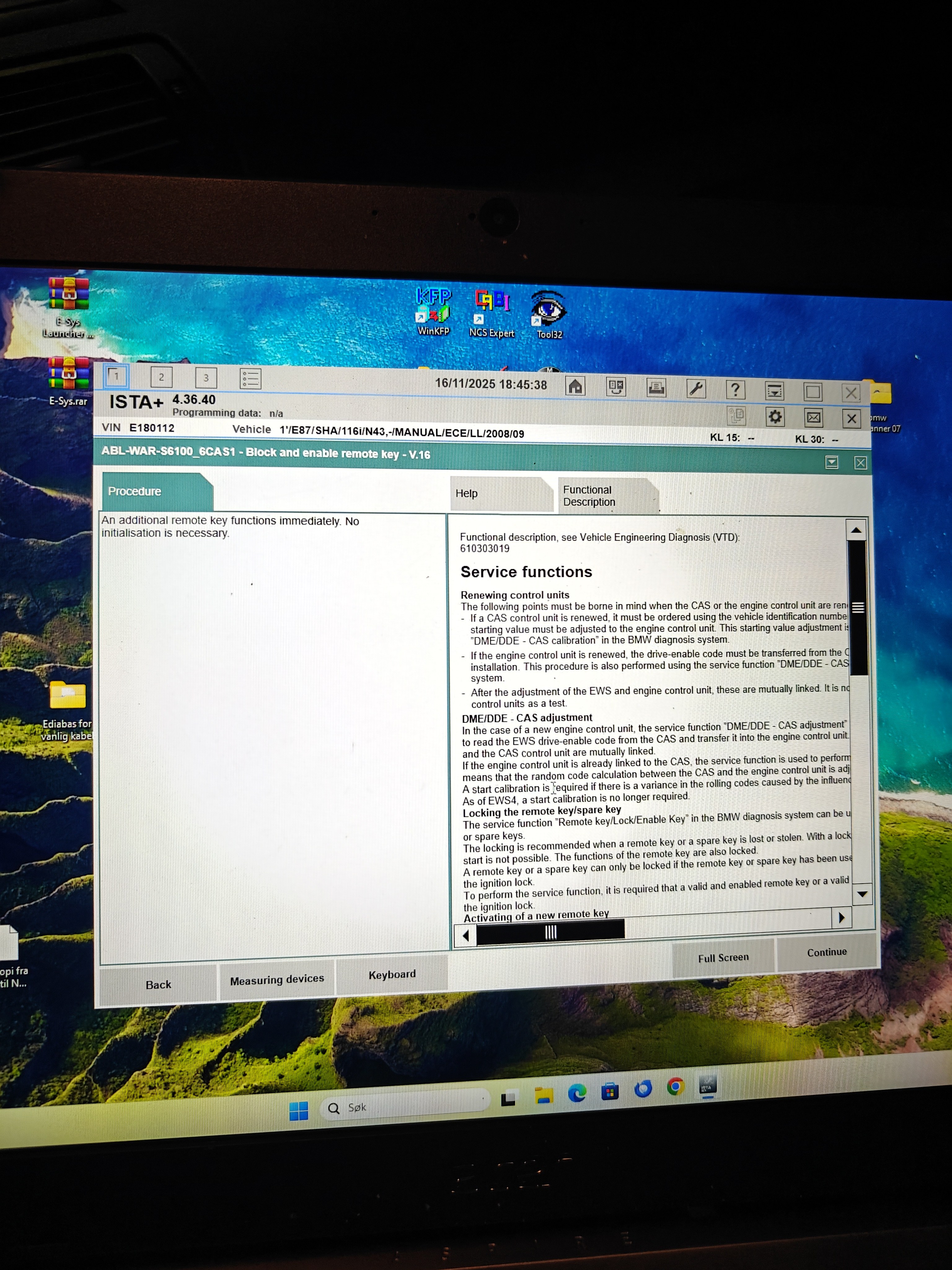
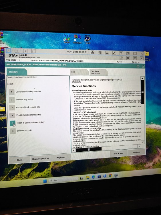
Hmm, blir ikke klok på dette, nå har jeg prøvd alt tror jeg, men tror rett og slett jeg må bare prøve og programmere en ny nøkkel til E60 for å teste der også, om ikke det virker der heller så må det jo være noen defekte Fob's jeg har fått. Ista sier at jeg skal la nøkkel sitte i "Slot" i 10 sekunder så skal nøkkel låse seg?? og når jeg velger "Teach in additional remote key" Så får jeg opp dette, hva nå det menes med dette er jeg ikke sikker på, men jeg vil nå tro at alle nøkler må aktiviseres for "Remote" bruk.

-
Nei, jeg tenkte kanskje det, men var ikke helt sikker, men hadde det fungert slik at man hadde fått den bekreftelsen på gammel nøkkel også så hadde kanskje den nye nøkkelen vært defekt, nå vet jeg ikke. Jeg kan jo alltids programere en ny nøkkel for og teste, eller kan man bare teste en blank nøkkel oppimot dørlåsinga, altså ikke programere nøkkelen, tenker siden det er 2 forskjellige system?
-
Ingenting som fungerer nå har jeg prøvd det meste av nøkkel aktivering som jeg har funnet på nett, samt sendt en melding til selger på Aliexpress så får vi se, nå skal det sies at det ikke skjedde noe når jeg prøvde med orginal nøkkel som fungerer heller, men kanskje det ikke skal skje noe når man prøver med orginal nøkkel? tenker da på opplåsing/nedlåsing som skal skje mens man går gjennom punktene.